Blog
How to Configure a Cylindrical LiFePO4 Battery Pack

TL;DR / Key Takeaways
- Series connections set voltage: 3.2 V per cell, so 4S = 12.8 V, 8S = 25.6 V, 15S = 48 V, 16S = 51.2 V.
- Parallel connections set capacity: total Ah = cell Ah × parallel count (P).
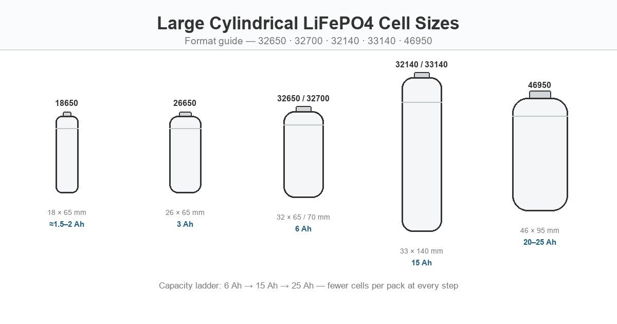
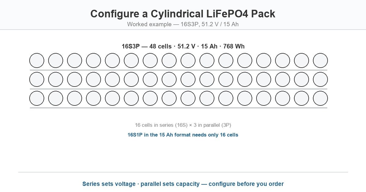
- Cell count = S × P, and it drives BMS channels, welds and assembly labor — the 6Ah 32700 needs 48 cells for 51.2 V / 15 Ah; the 15Ah 33140 needs 16.
- BMS sizing follows two numbers: channel count (equal to total cells) and continuous current (pack current plus margin).
- Cells in a string must come from one batch with matched OCV and internal resistance — mixing batches or brands is the most common cause of early pack failure.
Table of Contents
- [Step 1: Define the Pack Target](#step-1-define-the-pack-target)
- [Step 2: Set Voltage with Series Connections](#step-2-set-voltage-with-series-connections)
- [Step 3: Set Capacity with Parallel Connections](#step-3-set-capacity-with-parallel-connections)
- [Step 4: Count Cells and Choose the Format](#step-4-count-cells-and-choose-the-format)
- [Step 5: Size the BMS](#step-5-size-the-bms)
- [Step 6: Match Cells Before Assembly](#step-6-match-cells-before-assembly)
- [Step 7: Mechanical and Thermal Layout](#step-7-mechanical-and-thermal-layout)
- [Worked Examples](#worked-examples)
- [Common Configuration Mistakes](#common-configuration-mistakes)
- [Frequently Asked Questions](#frequently-asked-questions)
- [Final Thoughts](#final-thoughts)
Step 1: Define the Pack Target
Every configuration starts from three numbers, not from the cell:
- Nominal voltage — 12 V, 24 V, 48 V or 51.2 V class, set by the load or inverter.
- Capacity (Ah) — the energy reservoir, set by runtime requirements.
- Energy (Wh or kWh) — voltage × capacity; the number that drives cost and weight.
Write these down before choosing a cell format. The format decision comes fourth, and it is the only step where cylindrical size names matter.
Step 2: Set Voltage with Series Connections
LiFePO4 cells are 3.2 V nominal. Series connections add voltage; the count is simple division:
| Target voltage | Series count (S) | Nominal pack voltage |
|---|---|---|
| 12 V class | 4S | 12.8 V |
| 24 V class | 8S | 25.6 V |
| 36 V class | 12S | 38.4 V |
| 48 V class | 15S | 48.0 V |
| 51.2 V class | 16S | 51.2 V |
Two conventions coexist in the market. The “48 V class” is usually built as 16S (51.2 V nominal) because the extra 3.2 V headroom keeps inverter cut-off margins comfortable — the same reason most “12 V” packs are 4S at 12.8 V. Specify S from the nominal voltage, then confirm against the inverter’s voltage window.
Step 3: Set Capacity with Parallel Connections
Parallel connections add capacity. Total pack Ah = cell Ah × P, where P is the parallel count:
| Cell format | Cell Ah | For 15 Ah (P) | For 30 Ah (P) | For 100 Ah (P) |
|---|---|---|---|---|
| 26650 | 3 Ah | 5P | 10P | 34P |
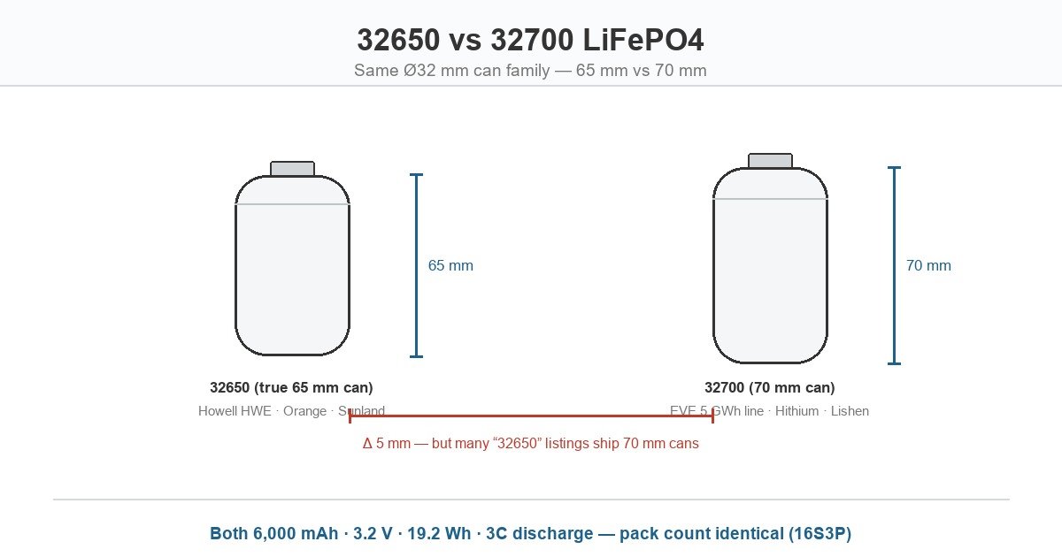
| 32650 / 32700 | 6 Ah | 3P | 5P | 17P |
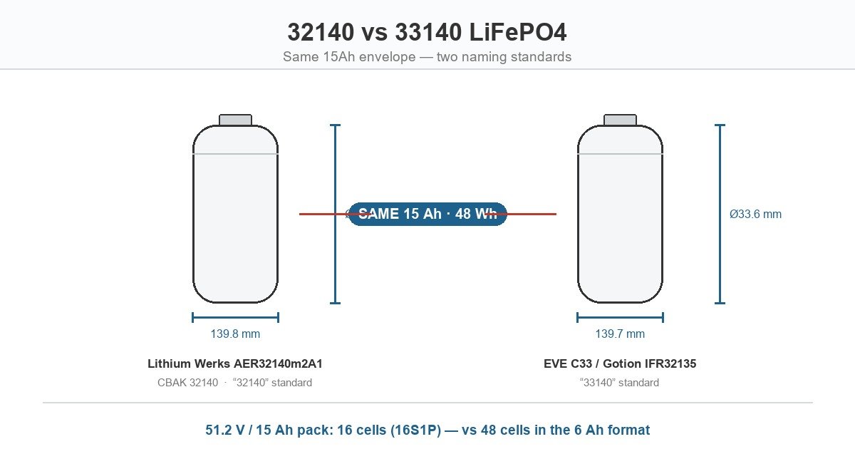
| 32140 / 33140 | 15 Ah | 1P | 2P | 7P |
| 46950 | 25 Ah | 1P (overshoot) | 2P (overshoot) | 4P |
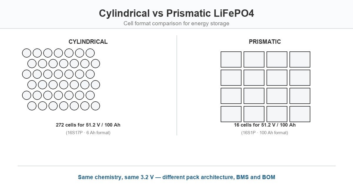
Two rules govern parallel design. First, parallel cells share current unevenly — internal resistance spread of even a few milliohms shifts load between branches, so parallel cells must be matched as tightly as series cells. Second, larger P multiplies the rebalancing burden on the BMS: a 16S17P pack has 272 channels to monitor, and any single weak cell degrades the whole parallel group.
Step 4: Count Cells and Choose the Format
Total cells = S × P. For the most common storage targets:
| Pack target | 26650 (3 Ah) | 32700 (6 Ah) | 33140 (15 Ah) | 46950 (25 Ah) |
|---|---|---|---|---|
| 12.8 V / 15 Ah | 4S5P = 20 | 4S3P = 12 | 4S1P = 4 | 4S1P = 4 (overshoot) |
| 25.6 V / 30 Ah | 8S10P = 80 | 8S5P = 40 | 8S2P = 16 | 8S2P = 16 (overshoot) |
| 51.2 V / 15 Ah | 16S5P = 80 | 16S3P = 48 | 16S1P = 16 | 16S1P = 16 (overshoot) |
| 51.2 V / 100 Ah | 16S34P = 544 | 16S17P = 272 | 16S7P = 112 | 16S4P = 64 |
Read the table as a cost map: every cell is a weld, a BMS channel and a warranty exposure. Moving from 6Ah to 15Ah format cuts a 51.2 V / 100 Ah build from 272 to 112 cells — a 59% reduction in assembly operations. The trade-off is granularity: a 16S3P 6Ah design can be re-configured to 7.5 Ah or 22.5 Ah by changing P, while a 16S1P 15Ah design is locked to its capacity step.
Step 5: Size the BMS
The BMS must cover two dimensions:
- Channel count = total cells. One voltage sense tap per cell, series and parallel alike. A 16S3P pack needs 48 channels; there is no way around this — it is why cell count drives BMS cost.
- Continuous current ≥ pack load current + margin. Size for the discharge current the load actually draws (charge current for the charge path), plus 20–30% headroom. For a 51.2 V / 5 kW inverter, that is ≈98 A discharge — a 100 A-class BMS at minimum, 120 A recommended.
Add temperature sensing at the pack’s thermal hot spot (not the average location) and confirm the BMS protection setpoints match the cell datasheet: over-voltage at the charge cut-off (3.65 V typical), under-voltage at the discharge cut-off (2.0 V), and over-temperature for both current directions.
Step 6: Match Cells Before Assembly
This is the step most first-time pack builders skip, and the most common cause of premature failure:
- Single batch, single maker, single model code. Never mix batches, brands or capacity grades in one string — capacity spread becomes a permanent imbalance.
- Sort by open-circuit voltage. Cells in a series string should sit within 10–20 mV of each other at rest; tighter is better for long strings.
- Sort by internal resistance. A milliohm or two of spread inside a parallel group shifts current between branches for the life of the pack.
- Document the lot. Keep batch codes with the pack record for warranty administration.
Grade-A suppliers issue per-lot capacity, IR and OCV test data with the shipment — ask for it, and build the sorting into the incoming inspection.
Step 7: Mechanical and Thermal Layout
- Cylindrical holders or fixtures with controlled compression. Cells expand slightly over life; holders must accommodate growth without crushing the can, and vibration duty needs positive retention (weld fatigue at the terminals is a known cylindrical failure mode).
- Can spacing for heat. Cylindrical cells shed heat radially; leave air channels between cans or specify forced airflow. At 3C discharge, a 25 mΩ cell dissipates roughly 8 W versus 2.6 W for an 8 mΩ cell — a difference the thermal design must absorb.
- Busbar and weld quality. Nickel strip sized for the continuous current, with consistent weld resistance across all joints.
- Insulation and fault containment. Physical separation between parallel groups, and a pack enclosure that can vent directionally in a fault.
Worked Examples
Example 1 — 51.2 V / 15 Ah (768 Wh) solar buffer, 32700 cells. S = 51.2 ÷ 3.2 = 16. P = 15 ÷ 6 = 2.5 → round up to 3P (18 Ah). Cell count 48 (16S3P), energy ≈922 Wh. BMS: 48 channels, sized for the inverter’s continuous current plus margin.
Example 2 — 51.2 V / 15 Ah (768 Wh) telecom backup, 33140 cells. S = 16, P = 1. Cell count 16 (16S1P), energy ≈768 Wh. Same pack target, one-third the cells — at the cost of format granularity.
Example 3 — 48 V class / 100 Ah (5.12 kWh) C&I ESS, 32700 cells. S = 16 (51.2 V nominal), P = 100 ÷ 6 = 16.7 → 17P (102 Ah). Cell count 272 (16S17P), energy ≈5.22 kWh. BMS: 272 channels; assembly labor and weld count become the dominant build cost — the case for evaluating the 15Ah format at 112 cells.
Common Configuration Mistakes
- Mixing cell formats or brands in one string — capacity and IR spread becomes permanent imbalance.
- Undersizing the BMS current path — size for peak inverter draw, not average.
- Ignoring charge current limits — a 0.2C-rated cell in a 1C charge profile will not reach full capacity and ages early.
- No batch matching — 50 mV of OCV spread in a 16S string is 0.8 V of imbalance to rebalance every cycle.
- Cramming cans without airflow — thermal design after the fact; see Step 7.
- Assuming 15S for “48 V” — most 48 V-class loads prefer 16S (51.2 V nominal) headroom; confirm against the inverter window.
Request a Quote
Frequently Asked Questions
How many cells do I need for a 48V LiFePO4 battery?
A 48 V nominal pack is 15 cells in series (15S); the more common 48 V-class build is 16S at 51.2 V nominal for inverter headroom. Capacity is set separately by parallel count — for example 16S3P with 6Ah cells gives 51.2 V / 18 Ah from 48 cells.
Can I mix cylindrical and prismatic cells in one pack?
No. Series strings require matched capacity, internal resistance, voltage curve and venting behavior. Mixing formats or brands in one string creates imbalance, uneven aging and unpredictable fault propagation. Parallel redundancy within a single model code is the accepted practice.
What BMS do I need for a 16S LiFePO4 pack?
A 16S BMS with one sense channel per cell — 48 channels for 16S3P, 16 for 16S1P — and a continuous current rating above the pack’s peak load (typically 20–30% margin). Protection setpoints should match the cell datasheet: 3.65 V over-voltage, 2.0 V under-voltage, temperature limits both directions.
How many 32700 cells for a 51.2V 100Ah battery?
272 cells: 16 in series for 51.2 V nominal, 17 in parallel for 102 Ah (16S17P). The same pack in the 15Ah 32140/33140 format needs 112 cells (16S7P) — the core cell-count economics argument for the larger format.
Do parallel cells need to be matched?
Yes, as tightly as series cells. Internal-resistance spread shifts current between parallel branches for the life of the pack, and a weak cell degrades its whole group. Sort by OCV and IR, keep a single batch, and request per-lot test data from the supplier.
What is the standard charge current for cylindrical LiFePO4 cells?
It varies by line: 0.2C–0.5C is common on 32650 listings (≈1.2–3 A for 6Ah cells), while premium 32700 lines accept 1C (6 A). A 1C charge recovers a full cycle in ≈2.5 hours versus ≈6 hours at 0.2C — check the datasheet, not the format name.
Final Thoughts
Configuring a cylindrical LiFePO4 pack is arithmetic before it is hardware: series sets voltage (3.2 V per cell), parallel sets capacity, and the product of the two is the cell count that drives BMS cost, welds and assembly labor. The format choice — 3Ah, 6Ah, 15Ah or 25Ah per cell — is really a choice about how many of those cells you want to build, balance and warrant.
Get the target voltage and capacity right, round parallel counts deliberately, size the BMS on peak current with channel count equal to cell count, and match cells by batch, OCV and IR before the first weld. CMX Battery supplies cylindrical LiFePO4 cells across the 6Ah, 15Ah and 25Ah classes with per-lot test data, and builds custom packs to configured specification — submit your target voltage, capacity and duty cycle through the inquiry form for a configured quotation within 24 hours.
Further Reading
- Large cylindrical LiFePO4 cell sizes: complete format guide
- 32650 vs 32700 LiFePO4: which cell fits your pack
- Customized cylindrical battery packs
- 32140 vs 33140 LiFePO4: the 15Ah dual-standard explained
- Cylindrical vs prismatic LiFePO4 cells for ESS
- Large cylindrical LiFePO4 battery cells — product hub
- Cylindrical lithium battery sizes: the complete guide